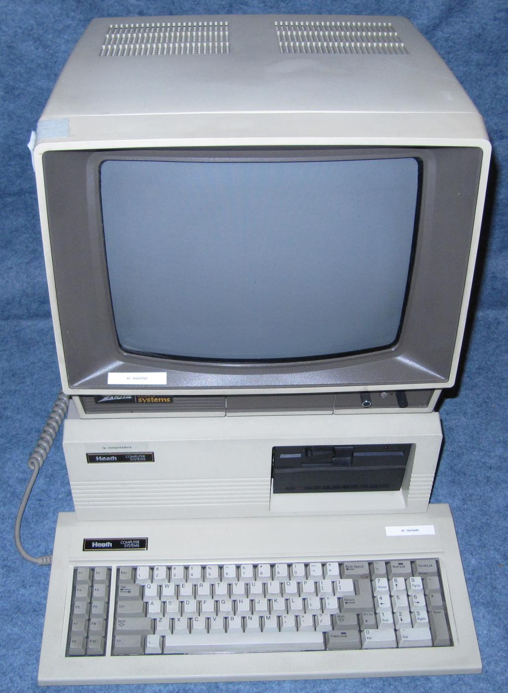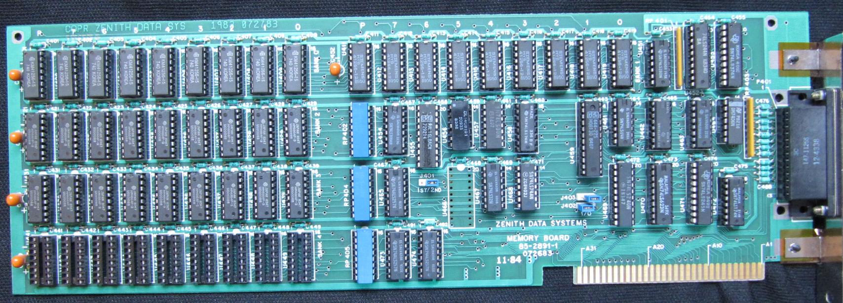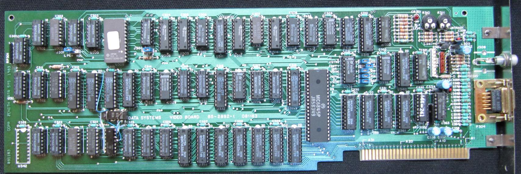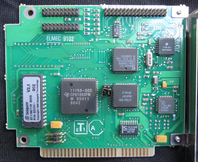
It was an IBM clone, meaning a computer sold by a company other than IBM, but designed to be capable of running software that had been written for the IBM PC. Click on the picture to see a larger version, and then in most browsers you can click again to see it even larger. Return here using your browser's "Back" button. It was not very common in those days to put a computer on the floor, on its side. It was placed on the desk in front of the user (which is why, of course, it was called a "desktop" computer). Thus, the picture shows the CRT ("Cathode Ray Tube") monitor perched on top of the computer, with the keyboard in front. One reason for having it on the desk in front of you was that you needed to constantly put in floppy disks, and take them out. As originally built, the computer had two 5¼ inch floppy disks, and no hard disk drive. The image above shows the computer later in its life, after one of the floppy disk drives had been replaced by a hard disk. Without a hard drive, when you changed from one program to another, you usually had to remove the disk of whatever program you had previously been running, and put in the disk of the program you were starting up. Longer programs took up multiple disks, and you often had to change them mid-stream as you performed various operations. The image below shows the central unit seen from above, with the cover removed and the parts labeled. You can click on the image to remove the labels and enlarge it, and click again to make it even bigger. 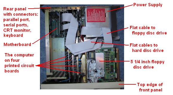 The Z-150 used the same technology as the IBM PC, of which it was a "clone". It was still not practical to put the entire computer on a single printed-circuit board, so it occupied four boards: a CPU board for the Central Processing Unit, a memory board designed to hold 320 Kbytes of RAM (Random Access Memory), a video board to drive the display, and a disc controller board capable of supporting two 5¼ inch floppy discs. I later removed one of the floppy drives, and upgraded to a 40 megabyte hard drive, with a small controller board that I plugged in to one of the expansion slots (the hard disk drive is underneath the floppy disk drive in the picture, but it's about the same size). 40 megabytes was a typical hard disk size at the time - it held everything I could possibly need. Note 1 The boards are interconnected by what is called a "motherboard" (also called a "backplane"), which runs left to right along the bottom of the case. You can see its left edge in the picture, with the words "ZENITH DATA" on the top, the first part of "ZENITH DATA SYSTEMS". You can see the upper-right corner of the motherboard just to the left of the power supply. You can see four green LEDs (Light Emitting Diodes) mounted on it. There are actually five of them. One of them lit up for each of the four voltages produced by the power supply, so you could see at a glance if one of the supply voltages had failed. The fifth lit a second or two after turning the unit on, indicating that all the voltages had come up properly, and the computer was being started. Why is it called a "motherboard"? Well, just take off the "d". On the right side of the picture below, you can see the belly of a mother boar (her feet are in the foreground):  Just as a mother boar provides nourishment to her babies, a motherboard provides power (from the computer's power supply) to all the boards plugged in to it. Here's a picture of the motherboard, also called a "backplane", with all the other boards removed (the wires on the right are bringing in power from the power supply): 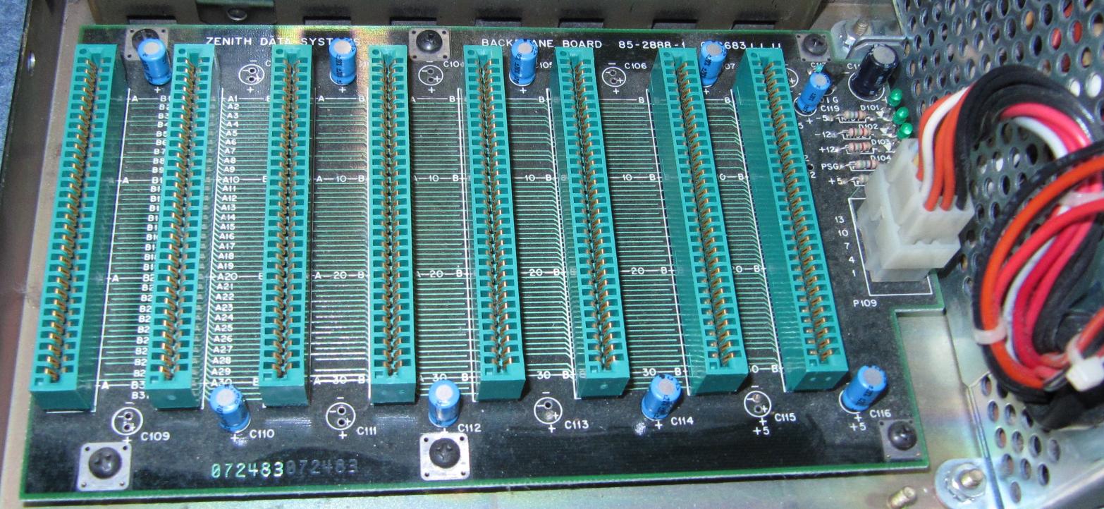 The motherboard's "teats", so to speak, are the green connectors seen in the picture above. A close-up of one of them is shown below to the left. Traces on each printed-circuit board come up to the edge of the board, on both sides, where they are gold-plated to be wear- and corrosion-resistant. This is called, naturally, an "edge connector", and one can be seen below to the right:  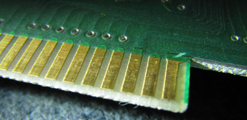 The image below shows a close-up of a board being inserted into a connector. It's only partially inserted in the picture. When it's fully "seated", the gold-plated traces will only slightly show over the top of the connector. 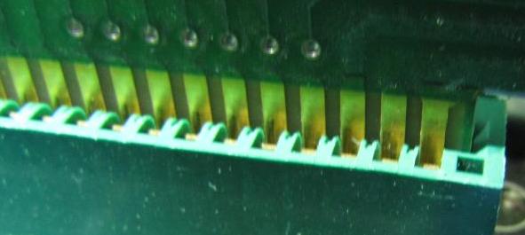 The traditional motherboard was only a backplane, distributing power and connecting signals between the boards plugged in to it. But the term became synonymous with any board that other smaller boards plugged in to. And as integrated circuits became able to put more and more components into a single chip, the entire computer moved on to a single board. But that board continued to be called a "motherboard", even though it now had little resemblance to a nursing animal. In a modern desktop computer, very little needs to be plugged into the motherboard, although it usually does accept memory expansion modules, graphics accelerator boards, or other specialty I/O (Input/Output) boards. The components in my Heathkit computer were mostly integrated circuits, whose chips were sealed into plastic "packages" called DIPs (Dual In-line Packages). In a commercially purchased computer, the DIPs were almost always wave-soldered directly onto the printed-circuit board. But in the Heathkit, I hand soldered sockets onto the boards, and only when all the soldering was complete did I "populate" the board by plugging in the actual DIPs. Here's a very-much enlarged photo of a typical dual in-line socket (left), and an integrated circuit that can be plugged in to it (right). Internally, the socket has spring-loaded connections that press tightly against the "pins" (the feet) of the DIP, making what's called a "gas-tight joint", and hence a good, and lasting, electrical connection. The pins are on tenth-inch centers (2.54 mm). 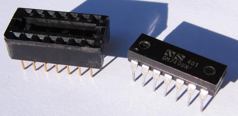 It addition to distributing power to the boards, the motherboard carries data signals between them. For example, for each access made by the CPU to the computer's memory, the CPU board sends the "address" of the desired data byte out over the motherboard on 20 address lines, and receives the specified byte back from the memory on 8 data lines. Finally, here are all the boards in the computer (click to enlarge):
I built all the above boards.
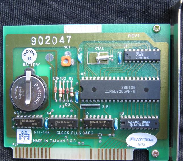
Note that the two added boards are smaller than the main boards of the computer. As the level of integration of integrated circuits increased from SSI to MSI to LSI (Small to Medium to Large Scale Integration), more and more of the logic went into the chips, and less size was needed for the boards holding those chips. These are commercially purchased boards - I didn't build them myself as part of the kit. The real-time clock board made it unnecessary for me to type in the date and time every time I started the computer. Remember, the information above describes a computer I built in 1984. Flash forward to more recent years. There's been an enormous push to miniaturization. Consider the transition from desktop computers to laptops, and then to notepad computers. Here's the inside of a defunct cellular telephone (click to enlarge it, and again to enlarge it even more). 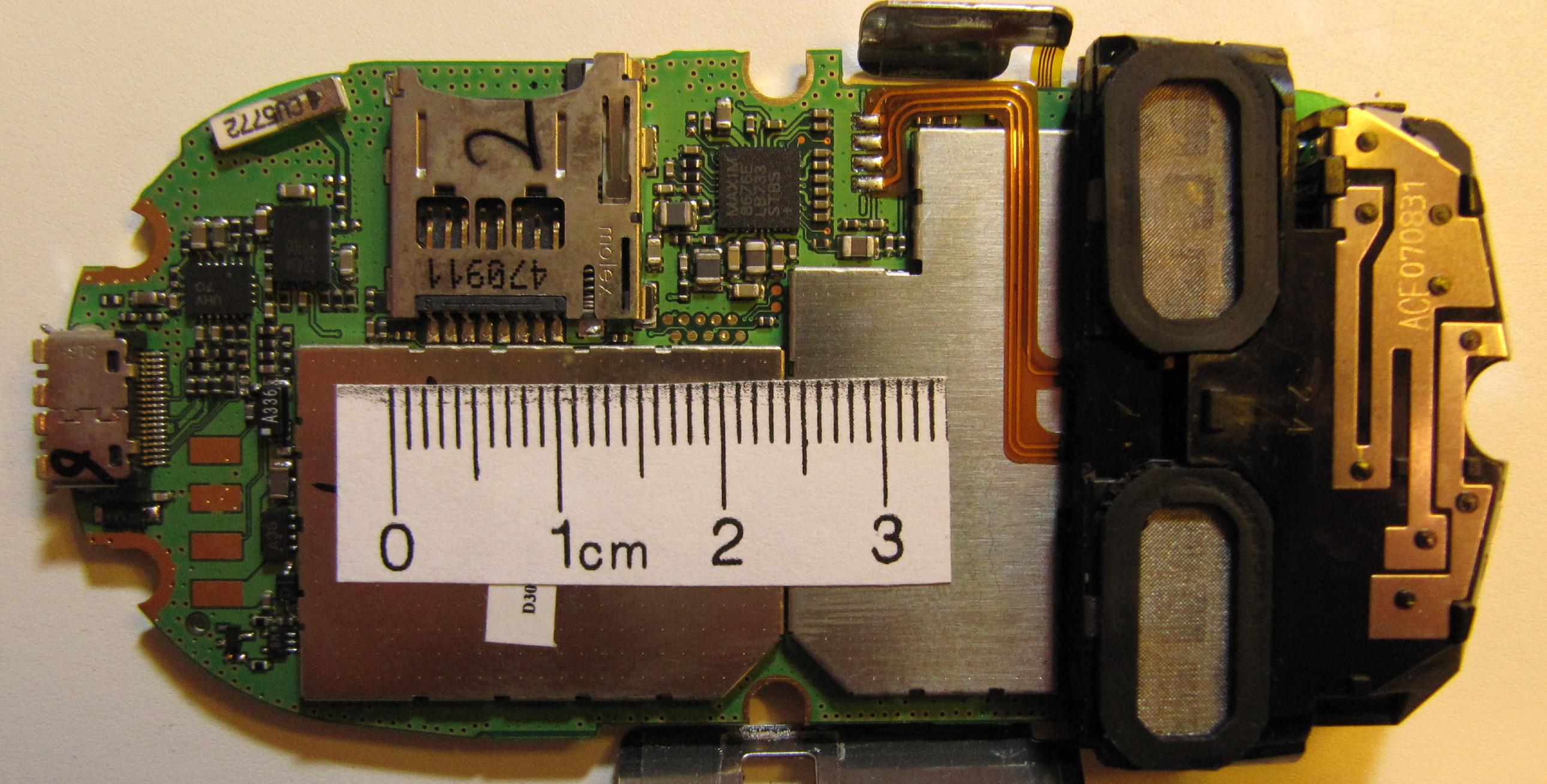 Because the phone contains a radio transmitter and receiver (I think that's the antenna on the right), much of that sensitive circuitry is shielded by a couple of metal cans. I've taped a small ruler over the cans to give you an idea of size (an inch is 2.54 cm). But you can see enough of the other components to get an idea of the density of the components and the wiring. All of the components are "surface mounted" - that is, their pins don't go through the board. Rather they are connected to tiny solder bumps on the top surface only. There's no way I could possibly build anything like that myself.
  Note 1: For those who want a bit more: For safety reasons (it contained high voltages), the power supply was included entirely assembled. It contained an actual transformer, so it was very heavy, especially compared with the light "switching" supplies of today, made possible by advances in high-voltage semiconductors. It was also quite large: 6 X 6.125 X 5.125 inches (15.25 X 15.55 X 13 cm). Taking in 110 volts AC, it produced +5V at 16.4A (Amperes), +12V at 5.4A, -12V at 0.25A, and had a separate highly regulated +12V supply at 1.5A for the dynamic memory chips. A "regulator" on the motherboard used the -12 volts to produce -5 volts at 100 milliamps, also for the memories. It has always struck me that the name "power supply" is a bit of a misnomer. Calling it a "supply" might be taken to imply that it supplies you power on its own, without having to be fed power from elsewhere. In that sense, an AA battery is a true "power supply". But what is usually called a "power supply" is not really a "supply" - it just changes the form of the power. As noted above, it takes in 110 volts AC, and "supplies" a number of different DC voltages needed by the circuitry. AC ("Alternating Current") is typically used mainly for power distribution (because the voltage can be easily boosted for transmission, using transformers), while DC ("Direct Current") is needed for electronic circuits. Because the computer was designed using American (English) units, in this blog entry I've reversed my usual convention, and give the English units dimensions first. The main boards in the computer came in two different lengths. The boards containing the CPU, video, and disk controller boards were 14.25 inches long (36.20 cm). The slots accepting the memory board, and other peripheral boards that might be added later (so-called "expansion slots) allowed for boards that were an inch shorter, 13.25 inches (33.66 cm). The boards were all about 4.44 inches wide (11.28 cm). The motherboard connectors had 31 connections on each side, for a total of 62. They were spaced on tenth-inch centers (2.54 mm). Clone computers, of course, used the same connectors used in the actual IBM PC, so that boards designed for that unit could also be used in the clones. This also meant that the voltages and timing of the signals on these connectors had to match those of the IBM unit. I used this computer for many years, until new programs coming out demanded faster machines. The final straw came when it couldn't run version 2 of the game "Leisure Suit Larry in the Land of the Lounge Lizards" fast enough to be usable. But that's another story. [return to text]
 |
