 Again, here's what I set out to do: Step 1: Determine how the Flight Simulator program was setting up the Color Graphic Adapter.
Step 1: Determine how the Flight Simulator program was setting up the Color Graphic Adapter. I did not have a software listing of the Flight Simulator software. It was a privately sold program, and the software (the "code") for it was not made available to the purchasers. The Color Graphics Adapter had quite a number of different modes in which it could be used, and I needed to know how the Flight Simulator program was setting it up for operation. But that was not especially difficult to find out. All of the registers of the Color Graphics Adapter were held in integrated circuits on the adapter's printed circuit board. I was able to run the Flight Simulator program, and then use a logic probe on my computer's video display board (the Heathkit/Zenith version of the CGA) to determine how these various registers were being programmed. I might note that it would not be possible to do this with a modern computer. In the machines of today, the entire video card has been shrunk down into a single "chip" (integrated circuit), so I would have no access to the internal logic. But in the technology of 1984, most of the logic was built out of chips that would now be described as "SSI" (Small Scale Integration). That allowed me access to the signals within the circuit. When I ran the Flight Simulator program and made measurements on the Graphics Adapter board, I found that it set up the board normally for operation in high-resolution color graphics mode, with one exception. When switching to flight mode, the program was "setting" (to 1, meaning TRUE) a control register bit that documentation for the IBM version of the Computer Graphics Adapter called "320 X 200 black and white graphics mode". Black and white!!?? The settings of other registers made it clear that the board was still operating in color. Why was the program setting a bit whose name, "BW", meant "Black & White"? The literature provided with genuine IBM PCs, which I had available to me at work, included complete circuit schematics of the computer's Color Graphics Adapter board, the electronic logic that created the image on the computer's CRT ("Cathode Ray Tube") display. And of course, Heathkit had also supplied me with complete circuit schematics of their version of the Color Graphics Adapter. As an electrical engineer proficient in digital circuit design, I would be able to trace out the circuitry, and find out what the differences were. Step 2: Figure out how, in an IBM PC, the settings used made the sky blue.
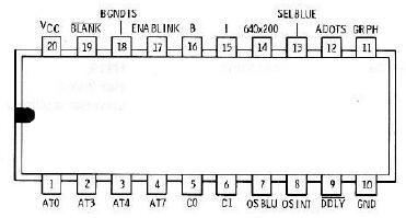
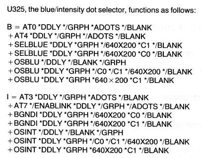
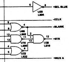
You can click on it to see one of the six pages of the schematic, as supplied by IBM (return here with your "Back" button). I can only find a somewhat degraded photocopy of the original manual, so I don't think it's worthwhile reproducing the whole thing. I'm showing it here just so you can get an idea what I needed to analyze to understand this digital circuit. Tracing out the logic, I discovered that when operating in color mode, there was only one effect of that "Black & White" bit being set in the control register. On the four-color "palette" of the CGA board in high-resolution display mode, it changed the color green to blue. So the programmer of Microsoft Flight Simulator must have figured that out as well, or perhaps found it out by experiment. And because he wanted to use blue for the sky, that's the setting he used. This use of an undocumented "mode" of the Color Graphics Adapter was the sort of trickiness that made the Flight Simulator a good test of how accurately clone computers reproduced the operation of a genuine IBM PC. OK, steps 1 and 2 understood: how Flight Simulator got the sky to be blue in an IBM PC. Step 3: Figure out why, in a Zenith PC, the same settings made the sky green. What difference caused that trick to NOT work in the Zenith clone? I figured I had only to trace out the corresponding circuitry in the Zenith computer to see why it responded differently. Why on earth did they not just copy the IBM circuitry exactly? And there, I got a bit of a surprise. Since the Zenith machine had been designed a bit after the IBM PC, new types of integrated circuits had appeared in the interim. Zenith had used a device called a "PAL", which stands for "Programmable Array Logic". It was a type of integrated circuit, new at the time, whose outputs could be "programmed" (electrically) to implement logical functions of its inputs. Once programmed (by electrically blowing tiny "fuses" inside the device), its operation was permanent. Zenith had replaced a handful of integrated circuits on their version of the Color Graphics Adapter with a single pre-programmed PAL device. Thus I couldn't trace out the logic on the Zenith board. Instead, I had to know the equations of the PAL, designated U325 on the board. Below is a drawing of the 20-pin PAL, as supplied in the Heathkit documentation, showing the signal name designations attached to each pin. The pins B and I are the only outputs. GND is the package Ground (0 volts), and VCC is the package power (+5 volts). All the other pins are inputs.  The equations of the PAL were also supplied, and are shown below, scanned from the Heathkit/Zenith manuals. In logic equations such as these, an asterisk (*, often replaced by a center dot) represents the logical AND function, and a plus sign (+) represents the logical OR. A preceding slash (/) represents negation, so that the signal /GRPH is 0 when GRPH is 1, and is 1 when GRPH is 0 (when hand-written, negation is usually indicated by a line over the symbol). 
Analysis revealed that Zenith had slightly changed the overall logic equations. The differences were slight, but they resulted in the BW (Black and White) setting in the control register producing no color change when operating in color mode. This was a miniscule change to an undocumented behavior of the Color Graphics Adapter, but it was a change that, as it was used by Flight Simulator, turned the sky green. But why hadn't Zenith programmed the PAL to reproduce the IBM behavior exactly? I realized that the PAL chip simply didn't have enough input pins. As noted above, it used two pins for power and ground, and it had two programmed to be outputs. It was in a 20-pin Dual Inline Package, so that left 16 inputs. It would have taken 17 inputs to reproduce the IBM equations exactly, and hence Zenith had changed the equations very slightly to eliminate the need for that 17th input signal. End of step 3 - I now understood the problem in complete detail. Step 4: Using hardware or software, fix it. Could I possibly do anything about it? Yes - return to the main entry to see how. In case you're curious: Every component on a printed-circuit board is given a name, usually a single letter followed by a number. Thus all the capacitors on a board might be numbered C1 through C37, and the resistors R1 through R46. A common designation for integrated circuits uses "U". "U325-13" refers to the integrated circuit DIP named U325, pin 13. Click the next link for a list of common component designations and symbols on Wikipedia. Writing the above, I became curious about why the designation "U" is often used for integrated circuits? I had never thought to ask that, but a little searching on the Internet revealed the following: "When [the] first IC's appeared, they were usually named micro-circuits, ... so U stands for 'micro'." Of course, you may still be asking, "Why does "U" stand for 'micro'?" Because a standard engineering symbol for "micro" is the Greek letter μ, named "mu". And it sort of looks like a U. Makes sense to me.   |
