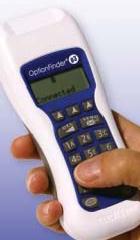
 I belong to ELVIS. That is, I've been appointed by the Town of Wayland to the ELectronic Voting Implementation Subcommittee. This committee is charged with implementing electronic voting at Wayland's open town meetings, attended by anywhere from a couple of hundred to a couple of thousand citizens.
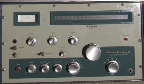
Although fairly expensive (it can cost around $30,000 to run one meeting with up to 1,500 participants), to an old-timer like me, it's almost miraculous that this can be done at any reasonable price at all. In my youth, the idea that every participant in a meeting would be given a small handheld device containing a radio transmitter (let alone a small computer) would have been out of the question. Of course, nowadays most people who own a car carry a small radio transmitter in their pockets, called a "remote entry device". These communicate with your car by transmitting a short burst of radio energy. Many people similarly carry (usually in their cars) small "remotes" for opening their garage doors without getting out of the car. But the old geezer in me wants to look at these small devices and say, "You call that a transmitter?".  That's a picture (which I've shown before in at least one earlier blog entry) of my old vacuum tube amateur radio transmitter, which I built in the mid-60s from a Heathkit. That's what a transmitter looked like in my youth, and you couldn't carry it in your pocket. It's about 49.5 cm wide by 28 cm high by 38 cm deep (actually, it was designed in inches, 19.5 by 11 by 15). Of course, even bigger transmitters are used by radio stations. We are so accustomed to electronic door openers that it's almost hard to remember a time when they didn't exist. But in my youth, a radio transmitter to cause your garage door to open would have been very large, would have used vacuum tubes, and would have consumed a great deal of power. It also would have been rather expensive. In the mid-50s, my father installed an electric garage door opener at our house, which opened and closed the door at the touch of a button just inside the garage's side entrance - it could not initially be commanded from the car. But somewhat later, he bought and installed a remote opener. Here's how it worked: a large cylindrical electromagnet, perhaps 8 to 10 inches long, was bolted to the car's front bumper, sticking down to about ten cm. (four inches) above the ground. Try to picture this gigantic thing - you had to be careful not to park head-in too close to curbs. The magnet was energized by a button inside the car. It drew quite a bit of current, enough to make the lights dim slightly when the button was depressed. A special magnetically activated switch was buried under the ground in the center of the driveway, which at that point (some distance from the house) was fortunately not paved. Note 2 So to close or open the garage door while leaving, or returning to, the house, you drove slowly over the spot where the switch was buried, while holding down the button to energize the magnet. You had to be sure the car was centered in the driveway, so that the magnet would pass more or less directly over the switch. Obviously, with all its installation difficulties and cost, this was not a commonly sold commercial product. It was installed mainly by technically oriented hobbyists like my father. That's what it took to remotely open a garage door prior to the invention of cheap transistorized transmitters. Boy, that was quite a digression for an entry called "Voting". Well, my mind wanders a bit. Note 3 So to get back to my original topic, lacking inexpensive transmitters and microprocessors, it wasn't always so easy to vote in a meeting. In the early 60s, I was elected to a few honorary societies at MIT. These were Sigma Xi, a scientific research society, Tau Beta Pi, an engineering honor society, and Eta Kappa Nu, an electrical engineering honorary society of the IEEE (the Institute of Electrical and Electronics Engineers). Once inducted into these, I participated the following year in their election of new members. Two of them used electronic voting machines to allow their members to vote anonymously, and yet complete their meetings in a reasonable amount of time (compared with the time needed to collect and count paper ballots). One of the honorary societies required something like a two thirds vote of the current members to admit candidates (or some similar quantum of vote). They therefore distributed voting buttons strung along fairly thick multi-conductor cables. The buttons could be concealed in your hand, so others couldn't see whether or not you were pressing it, making the vote anonymous. In those days, it would have been financially prohibitive to build a voting machine out of fully electronic circuitry to count how many buttons were depressed. Instead, the kind of "relays" used in old-fashioned telephone exchanges were used to build a voting machine. A "relay" is an electromechanical device activated when an electromagnet (a spool of wire wrapped around an iron core) magnetically pulls an "armature" towards itself when energized, opening or closing a set of attached switch contacts. Click here to go to HowStuffWorks.com to see a picture, and simple explanation of what makes them tick. That link will open in a separate window or tab, so you can explore the page, and then close the window or tab to return here. Note 4
The voting machine circuitry designed by the MIT students used multiple Strowger switches, stepping them through their contacts, and in each position sampling one of the buttons out on the voting floor. If the button was depressed, an electromagnetic counter was pulsed to record that vote, and then the Strowger switch moved on to the next button. The whole thing was extremely noisy, and not all that fast. For each vote, we were told to hold our buttons tightly depressed for the duration of the vote, while the Strowger switches made a loud machine-gun like noise as they sampled the buttons in the audience at a rate of several per second. I think the whole vote took 10 or 15 seconds. In practice, the machine required a lot of maintenance. The buttons had a problem with their contacts getting dirty, in particular because an electrical inductive "spike" was generated by the coil of the counter the buttons were activating. The resulting small spark tended to corrode the button's contacts. Each session started off by cleaning each button's contacts. Overall, voting was rather noisy and unreliable. The other honorary society had a simpler voting task, because they used a "blackball" system, in which a candidate could be refused admission if only two current members voted against him. This could have been done by a show of hands, but here it was also desired to have the voting be anonymous. Because of the "blackball" voting method, it was not necessary to actually count the number of votes cast. All that had to be done was to detect if two or more buttons had been pressed. If there were two or more, we didn't need to know the actual count. Therefore, a rather simple voting machine was used. A long cable containing two wires snaked back and forth through the chairs in which the audience was seated. At each seat, a resistor could be connected between the wires by pushing a button. A resistance measurement at the front of the room determined whether two or more buttons had been depressed. Note 5 The way a particular task is done always depends on the technology of the day. I remember thinking, as a young engineer, of all the great things you could do if every supermarket cash register had a CRT ("Cathode Ray Tube") display. But in my youth, the cost would have been out of the question, far too expensive. Not any more, of course. I talk more about the resistor-string "blackball" voting machine in my next two blog entries, called Schematics and Larry Black, so I hope you were paying attention. They teach you how to read an electrical schematic diagram, and talk about the wonderful mathematical beauty of linear circuit theory that drew me into electrical engineering, and hence changed my life. Don't worry - I keep it simple.
  Note 1: WiFi is the method used to get your laptop computer on-line at Starbucks. Although the voting handsets use same frequencies, they use a different communications "protocol". A frequency-hopping spread-spectrum protocol is used for enhanced security. [return to text] Note 2: Here's a bit more technical detail on the buried switch, for you techies. It was completely sealed for burial, but internally (according to a diagram that came with it), it had a seesaw-like assembly. There was a magnetic material such as iron on one side of the fulcrum, and a nonmagnetic material like copper on the other side. When the iron side was pulled up toward the magnet, the other side swung down, dipping into a pool of mercury and thereby making an electrical contact (when we shook the switch before it was installed, we could hear the mercury sloshing around). This switch was wired in parallel with the button that controlled the garage door, so that activating it was equivalent to pushing that button, thereby opening or closing the door. This switch might sound a bit bizarre, but there were sound reasons behind its design. There might have been a 10 cm. or so (4 inch) gap between the bottom of the electromagnet and the ground, and then perhaps 5 cm. (2 inches) of soil above the buried switch. At that distance, the magnetic force pulling up on the iron side of the seesaw was not all that great. This meant that the switch needed to be very sensitive. Its seesaw construction meant that the swinging part of the switch could be nearly in balance, with the iron side only very slightly heavier than the opposite side. It could thus be pulled up by a rather small magnetic force, dipping the opposite side of the seesaw down. But although a very small magnetic force could easily tip the seesaw, if that motion simply pressed two electrical contacts together, it wouldn't apply enough force to make a good low-resistance connection. These days, an optical sensor could be used, but back then inexpensive LED's and phototransistors didn't exist. Actually, LED's and phototransistors didn't exist at all, let alone inexpensive ones. So the easiest way to make a high current capacity electrical contact that required very little activation force was to dip a contact electrode into a pool of mercury. [return to text] Note 3: They say I have A.D.D., but they just don't understa ... Oh look, a chicken! [return to text] Note 4: Obsolete relays were donated to MIT by Western electric, the research arm of the Bell system. We were thus able to obtain these parts at no cost. The best-known organization at MIT that made extensive use of these free parts was TMRC, the Tech Model Railroad Club. It was there that I learned the Bell Labs "Detached Contact Notation" used to do effective logic design with relays (a now thoroughly obsolete skill). I'll have more to say about that powerful notation in a subsequent blog entry. [return to text] Note 5: Again, a bit more detail for the techies. Let's call the value of each resistor "R". At the head of the room, the resistance of the entire collection was measured by an ohmmeter. If no button was pressed, of course, the circuit would be open (infinite resistance). If one person in the room pushed his button, the ohmmeter would measure an overall resistance of R. This would not be considered low enough to exclude the candidate. But if two people pushed their buttons, the presence of two current paths would produce a resistance of R/2, which would blackball the candidate. If any additional buttons were pressed, the measured resistance would be even lower. It sounds really simple, but in actual operation, the device proved to be a little bit tricky. For one thing, there is an issue of what in electrical engineering is called "tolerance". Most off-the-shelf electrical resistors are not all that accurate, and their value can vary by plus or minus 20 percent. The resistance of one resistor which happens to be 20 percent too low is 0.8R, and the resistance of two resistors in parallel which happen to be 20 percent too high is 1.2R/2 = 0.6R, not all that different (this is called "worst-case analysis"). This problem can be solved by using more accurate resistors. If resistors are used which are accurate to within 5 percent of their designated value, then you should be able to distinguish without error between eight and nine buttons being pressed, and distinguishing between one and two is easy. And although 5 percent accurate resistors are a bit more expensive than 20 percent resistors, they are not prohibitively so. It's only when you start buying 1 percent resistors that the cost starts rising steeply - these are called "precision resistors". The other problem was the resistance of the switches. In principle, an idealized "normally-open" switch has zero resistance when the button is pressed ("closed"), and infinite resistance when the button is not pressed ("open"). In practice, a switch is apt to have a few ohms of resistance even when it is "closed". This issue is resolved by using resistors of a reasonably high value, perhaps several thousand ohms each, so that the resistance of the switches becomes negligible in comparison. However, since for simplicity and cost, the switch at each voting station was not packaged into a small box, but rather was just held in the user's hand, the switches tended to get a bit moist and to have a corrosion problem. If the contacts of a switch get really dirty or corroded, its "closed" (button depressed) resistance can get unacceptably high. Repeated cleaning and occasional replacement of the switches was necessary to keep the string in operating order. Clearly, this method was not as reliable as modern computerized voting terminals, but it served us reasonably well.
[return to text]
 |

 Some of you may recall (but some of you may not) that we once "dialed" each digit of a telephone number by placing our finger into the position on the dial corresponding to that digit, and swinging it around clockwise until it hit the stop. We then pulled our finger straight back out of the hole in the dial, allowing the dial to turn itself counterclockwise (driven by a spring) at a uniform rate of speed which was maintained by a small mechanical governor that was part of the dial assembly. This would generate pulses at a rate of 10 per second, the number of pulses being determined by how far the dial had been swung (that is, by the number dialed). Of course, we still speak of "dialing" a telephone today, even though very few phones have actual dials, but instead use buttons to generate "touch-tones".
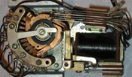
 Dial pulses were received at telephone central offices by a large relay called a Strowger switch, which had multiple contacts arranged in a circle. Each dial pulse magnetically pulled down an armature that in turn operated a ratchet, advancing the contacts of the Strowger switch one position around the circle. This effectively recorded, in the central office, the number that had been dialed at the remote telephone. These switches are, in fact, also called "stepping relays".