 I once drove my sister Phyllis from a Vermont ski resort back to Worcester, Massachusetts, where she was attending Clark University. Following a map (hey young people, there was once no such thing as GPS), we drove a route we had never taken before. Since I was driving, I handed the map to Phyllis as we approached some tricky turns. Phyllis, however, was uncomfortable, telling me she didn't know how to read a map. I gave her a short tutorial, and she caught on quickly. Soon she told me that the road was about to make a wide circle to the left, after which it would straighten out, and we would take the next left turn. We went around the curve, and sure enough, the road to the left appeared as predicted. Phyllis got very excited, saying something like, "I've got it now - the map is just like the real world, only smaller!" True, in a sense. But of course, the map is not really like the real world. Rather, it's a sort of schematic representation of the real world, in which lines represent roads, dots represent towns, and so on (there's a key to tell you what all the symbols mean). Here's an intersection near my house: 
My American Heritage dictionary defines "schematic" as "Pertaining to or in the form of a scheme or schema; diagrammatic." Want to learn how to read the schematic diagram of an electrical circuit? I'll keep it simple, and you'll be smarter than before. The following is not for the techies, who know this stuff already. It's for you non-technical readers, who usually skip this stuff. In my last blog entry, Voting, I described a "blackball" voting machine more or less as follows: "A long cable containing two wires snaked back and forth through the chairs in which the audience was seated. At each seat, a resistor could be connected between the wires by pushing a button. A resistance measurement at the front of the room determined whether two or more buttons had been depressed." You may recall that the machine needed to distinguish between one and two buttons pressed because two votes were needed to "blackball" a candidate. Here's the circuit diagram for the voting machine: 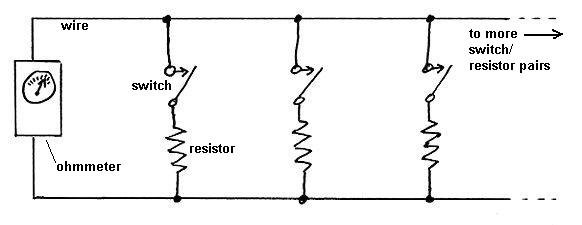 That kind of diagram is called a "schematic circuit diagram", or just a "schematic", for short. This one is very simple, having only three components: switches, resistors and an ohmmeter to make the resistance measurement. An ohmmeter contains a battery, so it's the source of the power needed to drive electrical current around the circuit (more on this below). What physical devices do the various symbols represent? Note 1  The photo above shows a switch and an electrical "resistor", under their respective symbols. There are actually many different types of switches, including the switches that control the lights in your home. The switch shown above is a push button stolen from an old keyboard (taking apart a discarded keyboard was once a good way of obtaining a lot of switches cheaply). You depress the key in order to close the switch, connecting the resistor into the circuit. Note 2
A resistor is a device that offers resistance to the flow of electrical current. The higher the resistance (measured in the unit "ohms"), the greater the electrical "force" (voltage) needed to push a given current through it, just as more pressure is needed to force water through a narrow pipe. It's also important to know that the lines shown on the schematic represent wires. Where two lines come together at a dot, the wires connect to each other, but if two lines cross without a dot, there is no connection. Here's a picture of some symbols, and the actual wires they represent: 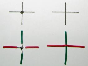 In each case, a red wire runs left to right, and a green wire runs up and down. These are copper wires covered by brightly colored plastic insulation. The copper conducts electricity, and the insulation blocks it. On the left, above, where these two wires cross, the insulation has been stripped off, to allow the two copper conductors to be connected by being "soldered" together. Solder is an alloy of lead and tin with a low melting point, which is melted to bond it to the copper at the point of connection. It then hardens, making a permanent electrical connection between the two conductors. The solder connection is represented by the dot in the schematic diagram above. On the right above, we also see two wires crossing, but in this case the insulation has not been stripped off. Because there's insulation between the copper conductors, although the outsides of the wires touch each other, there is no electrical connection. This is indicated by the lack of a dot on the schematic diagram.
The logic of omitting the dot is that there would be no reason to extend one line to just touch another unless a connection was intended. 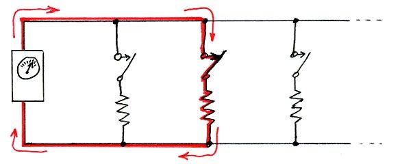 So, referring back to the schematic above, how does it work? The ohmmeter on the left applies an electrical pressure (commonly called "voltage", but more formally called "electromotive force") across the two wires connected to it, and measures how much current flows around the circuit. It's called a "circuit" (like a race car oval) because any electrical current must go around a closed path and return to its source. In this case, it can only do so if at least one of the switches is closed, as shown by the red path drawn on the schematic just above. The current will encounter resistance from the resistor it has to travel through. But the more switches that are closed, the more paths there are, and hence the lower the overall resistance measured by the ohmmeter (the amount of current that flows is proportional to the number of resistor paths available to it, and if the resistor values are all the same, the current will divide equally among the paths). Hence measuring the resistance can determine the number of switches closed (the number of votes). Now, here's an important difference between a road map and a circuit diagram. Because of what it's used for, a road map really must display distances accurately. It has a "scale" (for example, one centimeter on the map might represent one kilometer in the real world), and as Phyllis said, "The map is just like the real world, only smaller". Note 3 But in an electrical schematic circuit diagram, distances don't matter. There is generally no need to depict the actual layout of the circuit - all that matters is how it is connected. Remember the purpose of the circuit I'm discussing - a voting machine. Each switch/resistor rung on the schematic ladder had to be about 60 cm. (two feet) from the previous one. Here's an image of what one of the voting positions might have looked like: 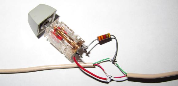 Notice that the two wires, which are red and green, are enclosed in an outer sheath for protection. The individual wires contained within the outer sheath are split apart only at each voting position, so that a connection can be made to the switch/resistor pair. The cable goes off in both directions to similar switch/resistor pairs one chair width to the right and to the left. None of these spatial details are of any importance for the schematic diagram - it only needs to show the electrical connectivity. By the way, in the real machine, there was insulating black electrical tape around all the connections - I've left it off to make the picture clearer. And now you understand what an electrical schematic diagram is. Note 4 Now, for an example closer to home. Actually, IN your home. Most homes have at least one light which is controlled by two wall switches, and now you know enough to be shown how that can be done. This involves a different type of switch, in which one terminal (a terminal is a connection point on the switch), called the "common", is connected to one of two other terminals depending on the direction the switch is thrown. The schematic looks like this:  The circle above on the left, with a wiggly line in it, represents a source of electrical power (it's the electrical panel, the thing with all the circuit breakers, often in your basement). The circle on the right (containing a spiral filament) represents a light bulb (with a jagged arrow to the side indicating light coming from it). You should be able to figure out the switch symbols, even though they are of a new type. They are called "three-way" switches, because they have three terminals (connection points). Since both switches are shown in the "down" position, contacting the lower of the two wires between them, you can see that a complete circuit is formed, and the light is illuminated. Now consider (below) the same circuit shown four times, showing the switches in all four possible combined positions: 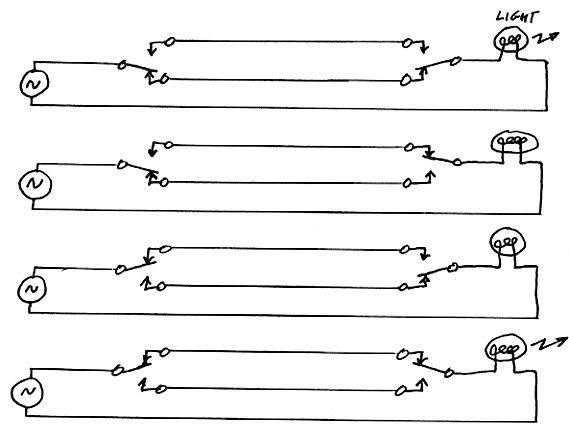 For this discussion, let's assume that the switches are installed so that the physical direction they are thrown actually matches their orientation on the schematic. In that case, note that if both switches are in the same position (down or up), they connect to the same wire, and the circuit is complete, lighting the lamp (you can imagine tracing a red line around the circuit - I don't need to do it for you). But if the switches are in different positions (one down and one up), they connect to different wires. Then there is no closed path for the current to flow around, and hence no "circuit" (the red line would have a gap in it). Current can't flow, and the light remains off. If you throw one switch, either from up to down or down to up, then if both switches were previously in the same position, they must now be in different positions (and the light, which was on, will go off). But if the switches were previously in different positions, they must now be in the same position (and the light, which was off, will go on). And that's exactly the behavior you want - throwing either switch will change the state of the light (turn it on if it was off, and off if it was on). Notice that the schematic shows you the essence of the circuit at a glance, and allows you to see how it works. The schematic doesn't bother with the actual physical layout - where the switches are in the wall, where the light is located, how the wires are grouped together in a common sheath, what the colors of the wires are, or any such details of the actual house or apartment wiring. A schematic circuit diagram only shows you the essential topology of the connections. Extra credit! If you're really sharp, you may have noticed that you could flip one of the switches upside-down, which would put a twist in the wires connecting the switches on the schematic:  If the switches are wired that way, then the light will be on if and only if exactly one switch is up. But the circuit will still function as desired in the sense that throwing a switch will always change the state of the light (on to off or off to on). Because of this, electricians usually install these switches without concerning themselves with which of the two connecting wires goes to which terminal. As a result, you may find that there are two ways any given light that is controlled by two switches behaves. Some of those lights might be OFF if exactly one of the two switches is up, while others might be ON if exactly one of the two switches is up. In each case, it depends on how the installer wired it (of course, whichever it is, once wired, the behavior will be permanent for that particular light and the two switches that control it). However, in my house, I've rewired a few of my switches, so that if you put all my up/down switches down, and all my left-right switches to the right, all my lights are off. Thus, if the power fails, I can easily turn off every light, including those controlled by two switches. I never have the problem of being awakened at three in the morning by lights coming on when the power returns. See? You're smarter now. Well, at least you know a little more. In my next blog entry, called Larry Black, I talk about the mathematical beauty of linear circuit theory, which is what drew me into electrical engineering, and hence altered the course of my life.
  Note 1: In an earlier blog entry, called Mr. Lusch, I included a story about a high school class that had learned how to draw the schematic of a particular vacuum tube circuit, but had never connected the symbols on the paper to actual physical devices. [return to text] Note 2: Back in the days when keyboards were very expensive, under each keycap was an actual physical switch, of considerable complexity. Nowadays, keyboards are very cheap, and a variety of tricks are used to sense multiple keycap depressions without having to use an individual switch for each key. [return to text] Note 3: The comedian Steven Wright once said, "I have a map of the United States ... Actual size. It says, "Scale: 1 mile = 1 mile." I spent last summer folding it." Not to be outdone in the map joke department, the comedienne Roseanne Barr noted, "Men can read maps better than women, because only the male mind could conceive of one inch equaling a hundred miles." [return to text] Note 4: Schematic aren't used only for electrical diagrams. Similar diagrams can be used for various other purposes. In his book Surely you're joking, Mr. Feynman, the brilliant physicist Richard Feynman told of an event that occurred when he was shown a set of schematic diagrams of an entire nuclear reactor. The drawings completely covered a large conference table, and were full of assorted symbols that were entirely unfamiliar to Feynman. He surmised that the lines on one diagram of the coolant system must have represented pipes, not wires. The lines were interrupted by small squares containing two diagonal lines, like an "X". Feynman guessed that those symbols probably represented valves. To test this theory, he picked one at random, and asked, "What happens if this valve gets stuck?" One of the nuclear engineers explained that the result would be that coolant would be cut off to an important part of the reactor, but the problem would be sensed automatically, causing a backup cooling system to turn on. At this point, another engineer noted that the particular valve Feynman had indicated was in a position such that its failure would not be detected by the automatic system, and in fact the backup cooling system would not be activated. As the engineers traced out the circuit, they realized that with no manual intervention, the failure of this single valve would result in a melt-down (something no single-point failure was supposed to provoke). The engineers looked at Feynman with awe from then on - he had stared at the schematics for a few minutes, and had identified a single valve whose failure could destroy the reactor. He had actually picked the valve at random, but of course he didn't tell them that. [return to text]
 |
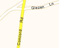 Now to the left, you can see that same intersection as it's depicted on a map. Looking at the picture above (in which you're driving north on Concord Road), obviously Concord Road is not a bright yellow line, as shown on the map. The map is a "schematic" representation of the real world, showing the essential features of the roads that one needs to navigate.
 Finally, a special case is shown to the left: a "T" connection will sometimes be shown on a schematic diagram without a dot. Nevertheless, a schematic "T" does indicate a connection between the wires - really, there should be a dot there, and there often is one.